Radial Flow Turbines: Outward and Inward Flow Reaction Turbines (With Examples)
The Outward Flow Reaction Turbine:
This turbine consists of a cylindrical disc mounted on a shaft and provided with vanes around the perimeter. At inlet water flows into the wheel at the centre and then glides through radially provided fixed guide vanes and then flows over the moving vanes. See Fig. 20.1. The function of the guide vanes is to direct or guide the water into the moving vanes in the correct direction. The water as it flows along the moving vanes will exert a thrust and hence a torque on the wheel. The wheel will thus rotate.
The water leaves the moving vanes at the outer edge. The wheel is enclosed by a water-tight casing. The wheel may run either in a horizontal or in a vertical position. The wheel may be provided submerged below the tail race level or may be provided above the tail race level and placed in a suction or draught tube. The latter arrangement is preferred as in this position the wheel is more easily accessible. Since this turbine is a reaction turbine, the water is under pressure and consequently the wheel must run full.
ADVERTISEMENTS:
As the wheel turns the body of water in the wheel is subjected to centrifugal action and increases the relative velocity of water in the outward direction. This results is increase in the rate of flow thus increasing the energy supplied. Consequently the speed of the wheel increases further. This will further increase the centrifugal head and the result is the wheel tends to race. This is a disadvantage in this type of turbine and controlling the speed of the turbine is, therefore, difficult.
Consider one of the vanes AB, A being the inlet and B the outlet of the vane. The inlet and outlet diagrams for the vane are shown in Fig. 20.2 (i). Note the peripheral velocity v at the inlet point A is along the tangent to the wheel at A. Similarly, the peripheral velocity v1 at the outlet point B is along the tangent to the wheel at B. Hence the vectors v and v1 are not necessarily in the same direction.
But for the sake of convenience the inlet and outlet diagrams are drawn as shown in Fig. 20.2 (ii). In this representation the vectors v and v1 are shown in the same directions. In this representation the outlet diagram as a whole appears shifted and, therefore, the sides and the angles of the triangle are not affected.
ADVERTISEMENTS:
Properties of the Outward Flow Turbine:
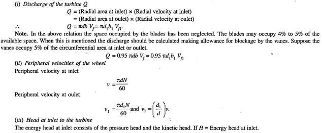
Let,
d = Inlet diameter (internal diameter) of the runner
d1 = Outlet diameter (external diameter) of the runner
ADVERTISEMENTS:
b = Breadth of wheel at inlet
b1 = Breadth of wheel at outlet
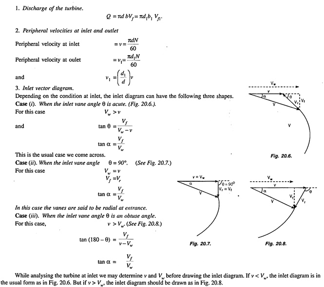
θ = Vane angle at inlet
ɸ = Vane angle at outlet
ADVERTISEMENTS:
α = Guide blade angle
= Angle between the direction of absolute velocity of water at inlet and the direction of motion of the inlet vane tip
β = Angle between the direction of absolute velocity of water at outlet and the direction of the outlet vane tip
V = Absolute velocity of water at inlet
ADVERTISEMENTS:
V1 = Absolute velocity of water at outlet
v = Peripheral velocity of the wheel at inlet
v1 = Peripheral velocity of the wheel at outlet
Vr = Relative velocity of water at inlet
Vr1 = Relative velocity of water at outlet
Vw = Velocity of whirl at inlet
Vw1 = Velocity of whirl at outlet
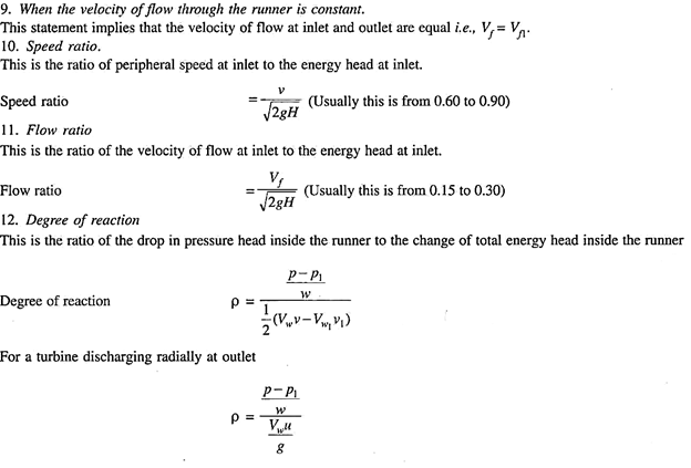
Vf = Velocity of flow at inlet (Radial velocity of water at inlet)
Vf1 = Velocity of flow at outlet (Radial velocity of water at outlet)
N = Speed of the wheel in rpm.
The Inward Flow Reaction Turbine:
The constructional details of this turbine are similar to those of the outward flow turbine but for the fact that the guide vanes surround the moving vanes. This is preferred to the outward flow turbine as this turbine does not develop racing. The centrifugal force on the inward moving body of water decreases the relative velocity and thus the speed of the turbine can be controlled easily.
Fig. 20.3 shows the components of the inward flow reaction turbine.
In this case the flow enters the surrounding guiding apparatus and flowing along the guide vanes enters the wheel at its outer periphery of the wheel of diameter d.
After moving along the runner vanes the water is discharged at the inner periphery of the wheel of diameter d1 i.e., the external diameter is the inlet diameter and the internal diameter is the outlet diameter.
Consider the moving vane AB, A being the inlet tip and B the outlet tip. Fig. 20.4 shows the inlet and outlet diagrams considering the vane AB. Note that the peripheral velocity v at the inlet point A is along the tangent to the wheel at A. Similarly, the peripheral velocity v1 at the outlet point B is along the tangent to the wheel at B.
Hence the vectors v and v1 are not necessarily in the same direction. But for the sake of convenience the inlet and outlet diagrams are drawn as shown in Fig. 20.5. In this representation the outlet diagram as a whole appears shifted and thus the sides and the angles of the triangle ate not affected.
This representation will be adopted in all the discussions to follow:
Properties of the Turbine:
The various properties of the turbine are given below:


