The following points highlight the top nine methods used for making threads. The methods are: 1. Casting 2. Rolling 3. Chasing 4. Die-Cutting 5. Self-Opening Die Heads 6. Taps 7. Milling 8. Grinding 9. Scru Broach.
Method # 1. Casting:
The method of casting screw threads is rarely used now-a-days as it results in a rough-thread. However, with the growth of shell moulding it seems reasonable to assume that this method will grow in importance. However, the chief disadvantage is that threads made by these processes must be made from a low melting point alloy; these are, therefore, soft and not durable for repeated use. When properly made, such threads have a good finish and a high degree of accuracy. Vending machines, sewing machines, type writer parts and toys may have threads cast in place.
For such cases, this method is very satisfactory because these parts are fastened together and rarely taken apart. Steel inserts may be cast in place and various parts such as helical inserts may be threaded into the hole to relieve the difficulty of having of parts wear too rapidly. It seems reasonable to assume that the future will show improvements in this field also.
Plastic moulding is employed for plastics only. This material may have threads cast in place, but most of the plastics are so easily worked that tapping will be more economical. Steel or brass inserts may be cast in place in this case also.
ADVERTISEMENTS:
Since lost-wax casting is often used for materials difficult or impossible to machine, it may be necessary to cast threads in this manner. The threads would be difficult to produce but would be of high accuracy and good finish.
Method # 2. Rolling:
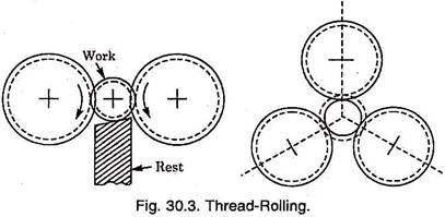
Rolling is the most economical and fastest method of making threads. It is actually a cold working process whereby a plastic deformation takes place. No metal is removed and no chips are produced. Cold rolling strengthens the thread in tension, shear and fatigue.
The fibres are not severed as in other thread making methods, but are elongated and reformed in continuous lines which increase the strength. Cold working always increases the strength of a material, its fatigue resistance and hardness. Surface finish is good.
The tools used are generally expensive, but die life is long and production of accurate threads can be maintained at high speeds over a long period. Thread rolling can be accomplished using either flat dies or circular dies.
The rolling of threads is not a new idea but has only recently surrendered to precision techniques. This method is confined to those parts which have external threads. It is not easy or practical to roll internal threads except in few cases, where diameter is large and the material is thin.
The majority of external threads produced are made by rolling. Such items as electric light bulb threads, wood screws, machines and cap screws, gimlet pointed stamped screws, sheet metal screws, hooks and eyes, as well as many parts are threaded and knurled by this process.
Flat dies are used in conjunction with special machines. The top and bottom dies are fixed over top and bottom slides, which are driven in opposite directions by hydraulic cylinders. The thread is formed complete within one pass of the blank between the dies.
Each die is grooved with the thread profile, the thread grooves being inclined as the thread helix angle to avoid interference during rolling. The die length is such that the blank rotates 4-5 times during one pass. Depending upon the material properties, the rolling speeds are between 0.50 to 1.25 m/sec.
ADVERTISEMENTS:
In the case of circular dies, these are contained in a die head. Three numbers highly polished thread rolls are mounted on large, friction free spindles. The thread grooves in the rolls are not annular, but are true helical grooves.
Method # 3. Chasing:
Thread chasing is the process of cutting a thread on a lathe with a chasing tool which in effect comprises of several single point tools blanked together in a single tool called a chaser. Fig. 30.4 shows a tangential type chaser for cutting external thread and Fig. 30.5 shows circular chaser to cut internal threads. This is relatively slow method of making a thread, since very little material can be removed per pass. Depending on the size of the thread, 20 to 50 passes may be required to complete a thread.
However, material removed can be minutely controlled, and this plus the adjustability of the tool means that size and fit can be minutely controlled. Therefore, when a broken or worn part needs to be replaced, the lathe may be an ideal machine on which it can be repaired.
Tight custom fits can be made on a lathe, as well as multiple threads, threads on tapers, threads on diameters not practical to thread with a die, threads that are not standard or those which are so seldom cut that buying a tap or die would be impracticable, or threads with a quick lead; all these are well suited for chasing.
This is only method of producing square threads, as other methods develop interference on the helix. When a work piece is to be machined in a lathe and also requires threads, internal or external but concentric with the turning operation, it is more economical to do the threading in the lathe either by chasing or with a tap or die.
Chasing lends itself better to non-ferrous materials rather than ferrous. Multi-start threads can be chased without any indexing of work piece. Taper threads can be generated by chasing, if chasing attachment is used in conjunction with taper attachment.
Speed and Feed:
ADVERTISEMENTS:
For the sake of smooth threads, the cutting speed should be as high as possible consistent with an economic cutter life between regrinds. For high speed steel cutters, speed of the order of 40 metres per minute and upwards should be used. The surface feed of the material being milled depends upon its quality and toughness and feed varies from 5 to 7.5 cm per minute for coarse threads in tough materials to 20 to 25 cm per minute under more favourable conditions.
For the most of the usual metals the relative directions of cutter and work relation are such as to cause the work to meet the cutter; but when milling certain metals such as aluminium, etc. smoother threads are obtained if the directions of rotations are so arranged that a cutter edge overtakes the work.
Method # 4. Die-Cutting:
This method is the most widely used method of producing external threads. Dies are relatively rapid producers and thus are economical. The quality and accuracy of such thread is only moderate but is acceptable for most mass produced articles. For a small shop, chasing may be less expensive than stocking a complete set of taps and dies.
Threading dies are of two general types:
(i) Bottom or Round Split Dies and
(ii) Adjustable dies.
(i) Bottom or Round Split Dies:
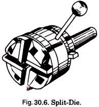
These are primarily intended for hand use but may be used in machines also. These dies are round with a radial cut closed by a screw which allows them to be adjusted within a narrow range for a tight or loose fit. These are held and operated by means of a die stock.
(ii) Adjustable Dies:
These consist of two pieces which are held in a collet or mounted directly in a die stock. By a taper arrangement these may be moved towards or away from the centre so as to provide various degrees of fit. They are primarily intended for hand use.
Method # 5. Self-Opening Die Heads:
Die boxes are used for high production of external threads on capstan and turret lathes. Die heads contain dies or chasers and each is suitable for a given range of sizes.
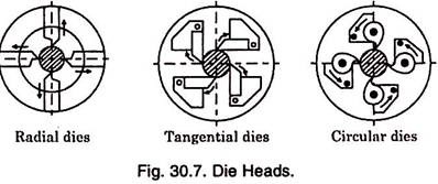
Three types of die heads commonly used are:
(i) Radial dies,
(ii) Tangential dies, and
(iii) Circular dies as shown in Fig. 30.7.
The dies open automatically when the required length of thread is cut. When the turret slide movement is arrested by a stop, the front part of the head continues to move forward by a small amount until the dies spring outwards, away from the work under the action of a scroll or cam.
Provision is made for taking roughing or finishing cuts by moving a detent pin to the appropriate position. Since the dies trip open after screwing operation, the work spindle need not be reversed in order to screw the die head off again. The dies can be closed by the operator after each screwing operation, by pushing a handle which partially rotates the front portion of the head.
Die heads for internal threads are collapsible taps. These withdraw or collapse inwards when a hardened steel ring around the tap strikes the end face of the work.
Threading dies are used for cutting or sizing external screw threads in a single pass. Dies are most widely used for cutting threads upto 52 mm in diameter.
A solid threading die (Fig. 30.8) is in effect a hardened nut with axial openings forming cutting edges. Normally, dies have from 3 to 6 clearance holes for chip disposal.
The die thickness is from 8 to 10 turns of the thread. The chamfer covers from 2 to 3 turns of the thread. The angle 2 j = 40° to 60° is for cutting through threads and 2j = 90° for cutting threads close to a shoulder. In standard dies the rake angle is g = 15° to 20°. The relief angle, which is α = 6° to 8°, is formed on the chamfered (cutting) section only.
Method # 6. Taps:
Available in many types, these are used for cutting internal threads. There are hand taps and machine taps, straight shank and bent shank taps regular pipe taps and interrupted thread pipe taps, solid taps and collapsible taps.
A tap may be compared with a screw which has teeth formed on it by cutting flutes parallel to its axis, and then has been hardened so that it will cut metals. Besides forming teeth, the flutes act as channels to carry away the chips formed by the cutting action.
Hand taps are furnished in three sets; taper, plug and bottoming. These three are identical in size, length and vital measurements, differing only in chamfer at the bottom end. The taper tap has about 10 threads chamfered at the end, the plug tap about 5 and the bottoming tap only 1. The taper tap allows the tap to be started straight in the hole easily so as to produce uniform and complete threads.
For threading purposes, these are used in the order; taper, plug and bottoming. Bottoming tap is best suited when blind holed threads are required. In cases where threads are to be made by using only one tap, the plug tap is generally used. Standard taps of sizes 5/32″ to 1/2″ are furnished with four flutes and are used for iron and steel.
These do not provide sufficient chip room for certain metals that are soft and stringly, such as copper in which case two or three-fluted taps should be used. Serial hand taps are also available and are similar to the above set except that each cuts only a certain percentage of the complete thread.
They are numbered 1, 2 and 3, and are used in that order. These taps find particular use in cutting tough metals because the load is shared by the three taps, making cutting easier and producing a smoother thread.
Nut taps are made with straight shanks (short or long) and bent shanks.
The thread length l of a tap (see Fig. 30.9) is made up of a chamfer l1 and a sizing section l2. The chamfer, or cutting section, has 4 turns of the thread for roughing hand taps, and 1.5 to 2 for finishing hand taps. Machine taps have from 5 to 6 turns of the thread on the same section for cutting through holes, and 2 turns for cutting blind holes. Nut taps come with chamfers having 11 to 12 turns of the thread.
The sizing section l2 of the tap serves to finish and size the thread being cut and properly guide the tool in the hole. This portion is slightly back tapered to reduce friction.
The shank l3 is a plain rod with the square l4 for hand (and sometimes for machine) taps. The profile of tap flutes has an effect on the cutting process and should facilitate the removal of chips. Taps with three and five flutes have found wide use.
The rake angle in taps is g = 5° to 10° for threading steels, g = 0° to 5° for cast irons, and g = 10° to 25° for non- ferrous metals and alloys. The relief angle is α = 4° to 12°. Taps are usually made with straight flutes, but for some applications resort is made to taps with helical flutes having a helix angle of ε = 8° to 15°, which improves conditions for chip removal.
Method # 7. Milling:
When threads are cut by milling, the thread is formed by a revolving milling cutter shaped to conform to the shape of thread desired. Either single or multiple cutters may be used. In the case of single cutter, all the cutting edges lie in one plane. The multiple cutter consists of several annular rows of cutting teeth.
A hob may be used for cutting threads, in which case the teeth lie along a helix. The disadvantage of the hob type cutter is that it must revolve with a fixed relation to the work, this is not true of the cutter with annular teeth.
Milled threads may be external or internal, the only limitation being the size of hole in which a cutter may be inserted. The threads cut by this method are more accurate than those cut by a die but not so accurate as those cut with a grinding wheel. A given cutter is not limited to one size of thread, as in the case with taps and dies.
This method is desirable when the pitch of the thread is too coarse to be cut with a die. This process is more efficient than threading on a lathe, especially when the work piece is long or when large amount of stocks are to be removed. Parts such as lead screws are milled because of the high accuracy and fast production and because the part can usually be finished in one or two passes.
The object of using multiple cutter is to complete thread in one revolution of the work. This can be done if the thread is not too long. In order to do this work, it is necessary to have a cutter which has one or two threads more than the work. If an annular cutter is used there is an annular row of teeth for each tooth groove, the work is completed in one pass with the cutter moving axially a distance equal to the lead of one thread, plus a small over travel to assure a complete thread.
Method # 8. Grinding:
Internal or external threads can be finish ground by means of a single or multiple edge grinding wheel. The threads are cut as grinding wheel (having annular thread grooves formed around (is periphery) and work rotate. A vitrified bond is generally used with a fine grit of about 60. The process is carried on a special grinding machine having a master lead screw and gears and means of holding the work.
The wheel rotates at 30 m/sec and work is rotated slowly. In the case of hardening stock probably grinding is the only means of forming threads. The accuracy of grinding exceeds that of any other method and the finish is exceeded only by good thread rolling.
Pitch diameters can be ground to an accuracy of ± 0.002 mm per 2.5 cm and accuracy of lead may be maintained within 0.007 mm in 50 cm of thread length. Grinding eliminates tiny cracks due to hardening and also tearing is always present to some extent in any material removal method.
Distortions due to heat treatment may be eliminated by grinding. Parts which would be distorted by milling threads can be satisfactorily ground. The thread parts which demand high accuracies and freedom from distortion, and stress cracks are usually made by this method.
Two variations of process are:
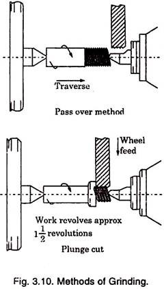
(i) Pass over or traverse method and
(ii) Plunge method.
In first method the wheel is positioned at full thread depth and then the work is traversed past the wheel. The work table traverse is controlled by a master lead-screw and change gears are used to suit the thread pitch.
The first thread form on the wheel gets worn out fast since it removes maximum metal and remaining threads effecting the finish. In the case of plunge cut thread grinding, the wheel is plunged into work to full thread depth. The work piece then makes one revolution and work traverses one pitch.
The grinding wheel has annular thread grooves around its periphery and these can be produced either by crushing or by diamond dressing. The accuracy of thread profile is very important. In the case of crushing, crushing roller of hardened steel having the required thread on it is fed into the wheel face under pressure and voluminous supply of lubricant as the wheel rotates slowly.
Method # 9. Scru Broach:
This is a newly developed process of thread cutting. It finds application in the automotive field. Parts such as internal threads on steering gear ball nuts, ball-race nuts for various circulating ball-type assemblies are the examples of this class. The work pieces are given one or two passes (rough and finishing cuts), heat treated and then finish ground on an internal thread grinder.
One station machines are used. The broaches used for the application have a special form and are guided by lead-screws. Threads are cut by drawing up the part and fixture against the revolving tool. The broaches are available in sizes upto 50 mm diameter and 750 mm length.


