The following article will guide you about how to design a gating system used in casting of metal.
Design of Gating System:
ADVERTISEMENTS:
The design of a gating system depends on both the metal and mould compositions. For example- an elaborate gating design is needed to avoid dross (e.g., oxides) in easily oxidized metals of low melting point such as aluminium.
For cast iron, however, a short path for the liquid metal is selected to avoid a high pouring temperature. The gating design for a ceramic mould is quite different from that normally used for a permeable sand mould. Broadly, gating designs can be classified into three categories, namely- (i) vertical gating, (ii) bottom gating, and (iii) horizontal gating.
In vertical gating, the liquid metal is poured vertically to fill the mould with atmospheric pressure at the base. In bottom gating, on the other hand, the liquid metal is filled in the mould from bottom to top, thus avoiding the splashing and oxidation associated with vertical gating. Figure 2.6 shows a simple vertical gating and a bottom gating design. In the horizontal gating system, additional horizontal portions are introduced for better distribution of the liquid metal with minimum turbulence.
Simple calculations based on principles of fluid flow can lead to an estimate of the time taken to fill up a mould. We shall illustrate this for the two designs in Fig. 2.6. The integrated energy balance equation on the basis of per unit mass flow, more commonly known as Bernoulli’s equation, will be used. For example- in Fig. 2.6a, it is assumed that the pressure at points 1 and 3 is equal (i.e., p1 = p3) and that level 1 is maintained constant. Thus, the velocity at station 1 (v1) is zero. Moreover, the frictional losses are neglected. Then, the energy balance equation between points 1 and 3 gives –
Equation (2.7) gives the velocity of a jet discharging against a static head h, making the effective head as (ht –h). now, for the instant shown, let the metal level in the mould move up through a height dh in a time interval dt, Am and Ag are the cross-sectional areas of the mould and the gate, respectively. Then,
ADVERTISEMENTS:
Aspiration Effect:
For a mould made of a permeable material (e.g., sand), care should be taken to ensure that the pressure anywhere in the liquid metal stream does not fall below the atmospheric pressure. Otherwise, the gases originating from baking of the organic compounds in the mould will enter the molten metal stream, producing porous castings. This is known as the aspiration effect.
Referring to Fig. 2.6a and applying Bernoulli’s equation between points 2 and 3, we obtain –
Another situation where aspiration effect comes into the picture is associated with a sudden change in the flow direction. As shown in Fig. 2.9a, the liquid metal stream contracts around a sharp corner due to the momentum effect. In vertical gating, this has got nothing to do with acceleration due to gravity.
The constricted region shown at station 2 in Fig. 2.9a is known as vena contracta. To avoid the creation of vacuum around station 2, the mould is made to fit the vena contracta, as done in Fig. 2.9b. In other words, a sharp change in the flow direction is avoided. If the runner diameter is d and the diameter at the entrance is d’, then, normally, d’/d is maintained at a value approximately equal to 1.3. This means r ≈ 0.15d.
The common items employed in a gating design to prevent impurities in the casting are as follows (see also Fig. 2.10):
(i) Pouring Basin:
This reduces the eroding force of the liquid metal stream coming directly from the furnace. A constant pouring head can also be maintained by using a pouring basin.
(ii) Strainer:
A ceramic strainer in the sprue removes dross.
(iii) Splash Core:
A ceramic splash core placed at the end of the sprue also reduces the eroding force of the liquid metal stream.
(iv) Skim Bob:
It is a trap placed in a horizontal gate to prevent heavier and lighter impurities from entering the mould.
Effects of Friction and Velocity Distribution:
The velocity of a liquid metal in the sprue and the gate is uniform across the cross-section. In fact, the velocity of a fluid in contact with any solid surface is zero and is maximum at the axis of the conduit.
The velocity distribution within the conduit depends on the shape of the conduit and the nature of the flow (i.e., turbulent or laminar). Further, in our discussion so far, we have also assumed no frictional losses.
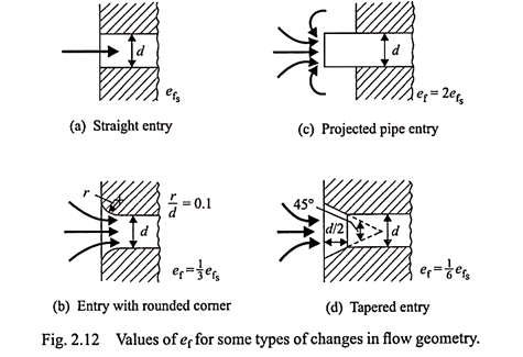
In real fluids, the frictional losses are always present, especially when there is a sudden contraction in or an enlargement of the flow cross-sections. In the discussion that follows, we shall, in the light of these two factors, i.e., velocity distribution and friction, modify the equations we have already developed.


