The torque is obtained by integrating the frictional force multiplied by roll radius over the arc of contact (lagging and leading zones).
The negative sign before the second term is due to the fact that in leading zone the metal moves faster than the rolls hence it helps to rotate the rolls. The above integration leads to rather complex calculations. To ease the situation we assume that the rolling load PT is acting at a distance ‘a’ from the centerline of the rolls. The distance ‘a’ is called the lever arm of PT (Fig. 7.13) and is expressed as a fraction of contact length L.
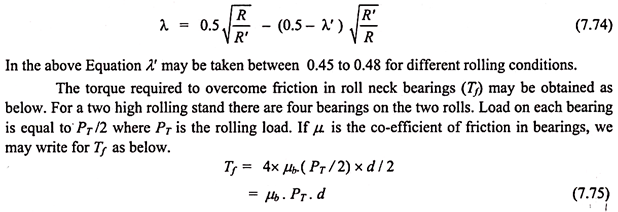
The value of λ has been calculated by Sim by calculating torque by Eqn. (7.71b) for a large range of rolling conditions. For hot rolling λ varies between 0.49 to 0.45. Lower values are for higher reductions. For cold rolling, the value of λ varies from 0.36 to 0.45. However, if we make the correction for elastic deformation of rolls and the increase in contact length, more accurate calculations can be made.
Hence, value of λ’ for cold rolling is calculated from the following relation-
ADVERTISEMENTS:
The modern rolling stands are powered by electric motors because precise and rapid speed control is possible. Except for bloom rolling and slab rolling stands, the power from motor goes to gear box for speed reduction and then to pinion box for distributing the power between two rolls (Fig.7.14). In slab rolling and bloom rolling mills, no gear box is used, motors are connected directly to rolls through universal couplings.
where
ADVERTISEMENTS:
Trm = Rolling torque which is converted to motor shaft taking into account the gear ratio between motor shaft and the rolls.
Tfm = Torque for overcoming friction in the roll neck bearing (converted to motor shaft).
Ttrm = Torque to overcome friction in transmission system (converted to motor shaft). The system may consist of couplings, gear box for speed reduction, pinion box for dividing of power between rolls etc. In each of these there is power loss due to inefficiency.
Tdynm = Torque required to accelerate the rotating masses during increase in rotational speed. In many rolling stands the rolling speed is increased after the start of rolling of strip. De- acceleration is done towards the end of rolling.
ADVERTISEMENTS:
The relationship between Tr -the torque required at the rolls and Trm (which is Tr converted to motor shaft) is the gear ratio (Gr) between motor shaft and the roll as illustrated below-
Example 1:
A 1000 mm wide and 2mm thick mild steel sheet is cold rolled to 1.5 mm thickness. The mean yield strength of the material of sheet is 25 kgf/mm2. The working roll diameter is 500 mm. Determine the rolling load on the rolling stand if the co-efficient of friction is 0.07. Also determine the rolling torque.
ADVERTISEMENTS:
A billet of area of section 150 mm x 150 mm is rolled to 120 height in a rolling mill with 600 mm roll diameter at a temperature of 1100 °C at 3m/sec. The yield strength of material — 90 N/mm2. The mill is driven by a motor which runs at 950 rpm and power is transmitted through a reduction gear box and a pinion box. The efficiency of gear box is 0.8 and of pinion box is 0.98. The co-efficient of friction in bearing = 0.06 and roll neck diameter = 360 mm. Determine the motor power required.


