In this article we will discuss about the design of inverted siphon with the help of a suitable diagram.
During laying of sewer lies in a town, at some places, the hydraulic gradient line falls above the ground surface. If there is more depression in the ground and the area is undeveloped or cultivated, sewer line can be laid above the ground by supporting on piers. But sewer cannot be laid above the ground at such places where road, canal and railway lines cross the sewer line.
To overcome such an obstruction in sewer lines, inverted siphons are provided. In an inverted siphon the hydraulic gradient line is above the flow-line, whereas in true siphon the hydraulic line is below the flow line. Inverted siphons are also known as depressed sewers, because the sewer portion at such portion is below the general sewer line.
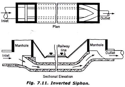
Fig. 7.11 shows the plan and sectional elevation of an inverted siphon. The pipe of inverted siphon must be able to withstand the internal pressure. The pipe diameter should be such that sewage may flow with great velocity.to avoided silting.
ADVERTISEMENTS:
In very large single pipe it is difficult to obtain high velocity for very small quantity of sewage. Therefore, in inverted syphon two or more pipes are laid in parallel as shown in the figure which come into action singly or combined in proportion to the amount of flow.
In minimum dry weather flow only one pipe comes into action and takes sewage at required velocity. The second pipe carries the difference between the minimum and maximum dry weather flow, and the third one carries the storm water. In the multiple pipe siphon, the inlet should be such that the pipes come into action successively as the flow increases.
This is achieved by providing lateral weirs with heights kept in accordance with the depth of flow at which one or more siphon pipes function. The inverted siphons are generally constructed of cast iron or R.C.C. At the ends of the inverted siphon manholes are provided for inspection and cleaning purposes.
ADVERTISEMENTS:
Both inlet and outlet should be given such a slope that the sewage can easily flow. The design of inlet and outlet chambers should allow sufficient room for entry for cleaning and maintenance of siphons. The outlet chambers should be so designed as to prevent the back-flow, of sewage into pipes which are not being used at the time of minimum flow.
Proper bypass arrangements should be provided from the inlet chamber to a nearby stream if permitted by the pollution control authority; otherwise special arrangements should be made for pumping the sewage to the lower reach of the sewer line. If long inverted siphon is provided in Wide River, hatch boxes with vent pipes should be constructed at 100 m intervals for rodding and preventing air locking.
The design of the inverted syphon will be clear from the following solved example:
Example:
ADVERTISEMENTS:
Design an inverted syphon of a total length of 80 m, to he provided for a 100 cm diameter sewer. The discharges which it has to carry are 0.72 cu.m./sec., 0.31 cu. m./sec. and 0.093 cu. m./sec., for maximum, average and minimum discharges respectively. The difference in levels between the inverts of the inlet and outlet manholes is 0.60 m. Adopt suitable self-cleaning velocity.
Solution:
Three separate sewers shall be designed to carry the discharge in the following way:
(a) One pipe shall be designed to carry the minimum flow = 0.093 cu.m./sec.
ADVERTISEMENTS:
(b) One pipe shall be designed to carry the remaining of average flow
= 0.310 – 0.093 = 0.217 cu.m./sec.
(c) One pipe shall be designed to carry the remaining of the max. flow.
= 0.72-0.31 =0.41 cu.m./sec.
ADVERTISEMENTS:
The inclined length of each of the pipes shall be
= √802 + 0.552 = 80 c.m
Adopting self-cleaning velocity = 100 m/sec. approx.
The sizes of the various pipes shall be determined as follows:
... Q = A. V.
... A = Q/V
(a) Cross-sectional area of the sewer pipe required to carry the minimum flow:
Ai = Q1/V = 0.093/1.00 = 0.093 sq.m.
Or π/4.d21 = 0.093
... d1 = √0.093/0.785 = 0.3442
Provide pipe of 30.0 cm diameter pipe. Ans.
Then the developed velocity
= 0.093/(π/4) × (0.3)2 = 1.316 m/sec. Safe.
(b) Cross-section area of the pipe required to carry the remaining of the average flow:
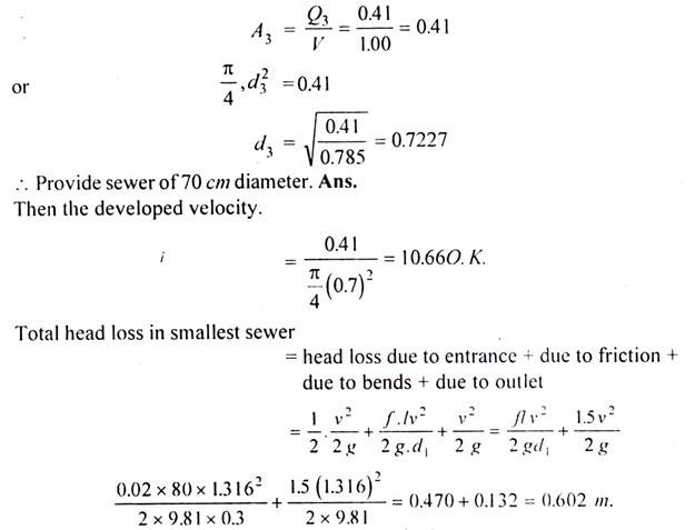
(c) Cross-sectional area of the pipe required to carry the remaining of the maximum discharge:
The outlet invert level should be lower than the inlet by the amount equal to the total head loss during the, flow in the smallest pipe i.e.: 60 cm Therefore, the difference already kept is the same i.e. 60 cm. Hence the design is O.K.


